We have already seen in the earlier posts about how to jam the mobile signals using simple mobile jammer circuit. Now, In this post, we are going to know about another interesting concept i.e. TV Remote jammer circuit. It is designed using NE555 Timer IC.This proposed TV jammer circuit confuses the infrared receiver in a TV by producing the constant signal that interferes the remote control signal. If you switch on the circuit once, the TV will not receive any command from the remote. This allows you to watch your own program without anyone changing the channel or volume.


The fundamental technology used in TV Remotes is Infrared light. This infrared light is invisible to the human eye, but we can see these IR rays through camera.
TV Remote Control Jammer Circuit Principle:
The idea behind TV remote control jammer is sending a constant IR pulse with the carrier frequency of the transmitter. Hence the result will be non-accepted signal from the receiver and therefore no action will be taken.
Basically the TV remote emits a sequence of pulses when you press a button. IR transmitter is fixed to the surface of the TV remote. This IR transmitter emits the pulses in unique configuration for each button.
IR receiver which is arranged to TV will receive these sequence of pulses that are transmitted by TV Remote and identifies which button is pressed in TV remote.
Generally Philips TV remotes follows RC5 (Remote Control) protocol. This protocol was developed by Philips in the late 1980s. According to this protocol, for each button, Remote transmits 14 bits. The below figure shows the frame format of RC5 protocol.
RC-5 Frame Format
The first two pulses are start bits, and both are logic 1.
The 3rd bit is toggle bit. This bit toggled every time when a button is pressed or released. Using this bit, we can identify weather the button is pressed or not.
The next 5 bits represent the device address. Bit 4 is the MSB of the device address and bit 8 is the LSB of the device.
Last six bits in the frame format are command bits. These command bits varies for each button in the remote. Using these command bits, we can identify which button is pressed in IR remote.
Features of RC5 protocol:
- Bi-phase coding (Manchester coding)
- 36Khz or 38Khz carrier frequency
- Constant bit time of 1.778ms
- 5 bit address and 6 bit command length
Modulation: The RC5 protocol uses bi – phase modulation. All 14 bits are equal length of 1.778ms.
TV Remote Control Jammer Circuit Diagram:
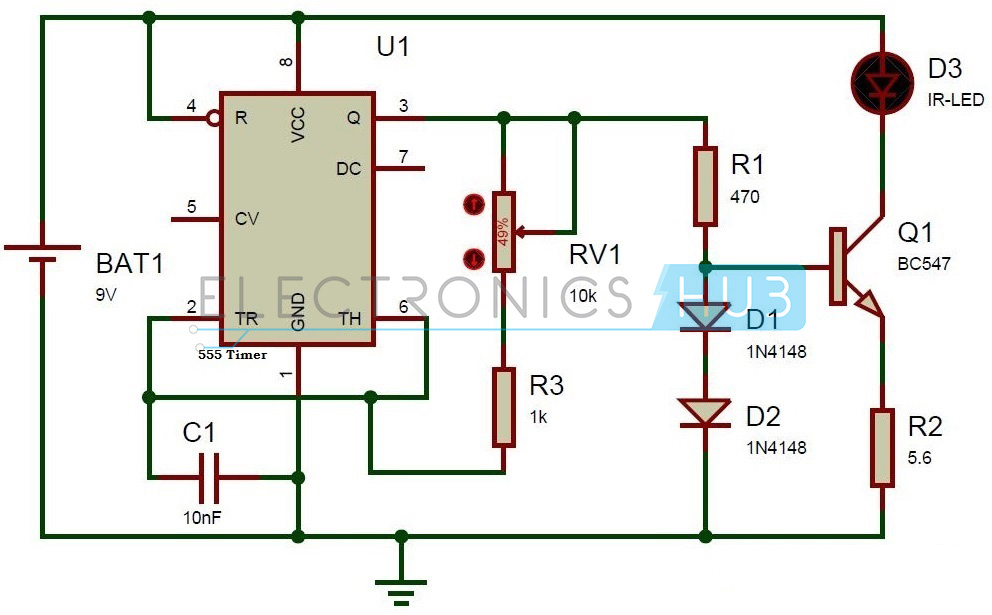
Circuit Diagram of TV Remote Jammer using 555 Timer IC
Circuit Components:
- NE555 timer
- 1n4148 diodes -2
- Resistors – 470 ohm, 1k, 5R6
- Pot – 10k
- 9V Battery
- Ceramic capacitor – 10nF
- Transistor – NPN
- IR – LED
TV Remote Jammer Circuit Design:
The circuit is designed to produce a 38 KHz signal. The main component in this circuit is 555 Timer. Here, it is operated in astable multivibrator mode. In this circuit, 2nd and 6th pins are shorted to allow the triggering after every timing cycle and these two pins are grounded through the capacitor. 4th pin of 555 timer is connected to supply to avoid sudden resets.
10k pot is used to adjust the frequency of 555 timer. The current through the IR-LED is limited to 100mA because of two 1n4148 diodes, as these form constant current arrangement when combined with transistor and resistor.
How to Operate this TV Remote Control Jammer Circuit?
- Connect 9v battery to the circuit.
- Now adjust the pot 10k to produce 38 KHz signal.
- Now press the TV remote buttons.
- You can observe that TV will not receive any commands from remote
- Disconnect the battery from circuit and press TV remote buttons.
- Now you can observe that TV will receive the commands from Remote
TV Remote Control Jammer Circuit Advantages:
- We can use this circuit to jam the remote signals so that the other people cannot change the channel while watching our favorite program on TV.
- It will not affect the signal receiving capacity of the TV.
Limitations of the Circuit:
- The circuit should be tuned correctly to 38 KHz frequency to get accurate results.
No comments:
Post a Comment