This is the simple and cost effective automatic emergency light circuit with light sensing. This system charges from main supply and gets activated when main supply is turned OFF. This emergency lamp will work for more than 8 hours.When power supply is turned OFF, the circuit senses the day light and according to the light it turns on the LED’s. If the light is present even though power fails the circuit turns OFF the LEDs. Here LDR (Light Dependent Resistor) is used to sense the light.

Automatic Emergency Light Circuit Principle:
When power supply is available, battery charges through the diode D2. At the same time white LED’s will glow based on the light conditions. When power fails, the white LED’s which are connected MOSFET will glow based on the light condition till the battery shuts down.
When LDR (Light Dependent Resistor) is in light, the resistance of LDR is very low. As a result base of the transistor Q1 becomes high. As a result white LED’s which are connected to MOSFET turns OFF.
When the circuit is in dark, the resistance of LDR is in order of mega ohms. Now the base of the transistor becomes low, as a result transistor Q1 switches the white LED’s to ON state.
Also read the related post: Automatic Washroom Light Switch Circuit
Automatic Emergency Light Circuit Diagram:
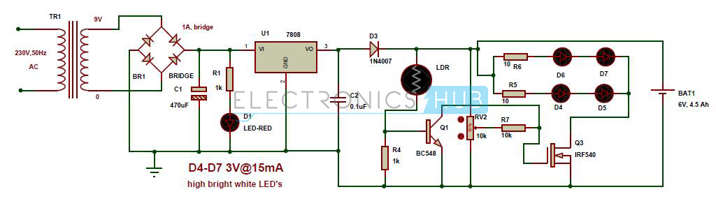
Automatic Emergency LED Lights Circuit Diagram
Circuit Components:
- 9V step down transformer
- Diode bridge – 1A
- 7808 voltage regulator
- Light dependent resistor – 2M ohm
- IRF540 MOSFET transistor
- BC548 PNP transistor
- DC battery – 6V, 4.5Ah
- Pot – 10k
- 4 high bright LED, s – 3v@15mA
- red led
- 1n4007 diodes – 1
- electrolytic capacitor – 470uF
- ceramic capacitor – 0.1uF
- 1k resistors – 2
- 10 ohm resistors – 2
- 10k resistor – 1
Automatic Emergency Light Circuit Design:
Here step down transformer is used to reduce input AC voltage to low AC voltage. Diode Bridge is used to convert input AC voltage to pulsating DC. Here capacitor C1 is used to remove the ripples from the rectified DC. LED D1 indicates the main supply and resistor R1 is used to protect the LED D1 from high voltage.
In this circuit transistor Q1 switches states white LED’s based on the supply as well as light conditions. The output of LDR is connected to the base of transistor Q1 to switch the transistor based on the light conditions. The collector terminal of the transistor Q1 is connected is connected to the gate of MOSFET to switch white LED’s according to the conditions.
In this circuit voltage regulator 7808 is used to regulate voltage and current. This IC has built in current limiting circuit. The output of this voltage regulator is positive 8V.
2 white LED’s are connected in series, so two white LED’s glow with the current that is required for a single LED. As a result energy is saved. For a white LED we need a minimum of 3.6V and maximum of 20mA current.
How to Operate Automatic Emergency Light Circuit?
- Give the connections according to the circuit diagram.
- While giving the connections, take care in such a way that there is no common connection between AC and DC supplies.
- Apply the main supply to the circuit, now you can observe that LED’s will not glow and battery will charge.
- Remove the AC supply and place circuit in dark, now LED’s will glow.
- If you place the circuit in light, then LED’s turns OFF.
Advantages of Automatic Emergency Light Circuit:
- This is very simple circuit and the cost is also very less.
- power is saved because the circuit switches the LEDs based on light conditions
Automatic Emergency Light Circuit Applications:
- Used in child’s study rooms to avoid the sudden power failure.
- As an emergency lamp in homes.
- Used in security systems to switch ON the lights automatically during the power failure.
No comments:
Post a Comment