This article explains you how to control the electrical appliances using an Android device. We have already seen how a DTMF controlled home appliances system works
in the earlier post. Operating conventional wall switches is difficult
for physically handicapped or elder people. This project provides the
solution to this problem by integrating all the electrical appliances to
a control unit that can be operated by an Android application device
(Android smart phone or Tablet). Proposed system controls the electrical
loads based on the data transmitted by the Android device. An android
application should be installed in user’s mobile or tablet to control
the electrical loads. Using this android application user can send the
commands to the Bluetooth module to control the electrical loads.
Wireless technology used in this project is Bluetooth. It can also be
called as “Android based Home Automation System” or “Remote Password
Operated Electronic Home Appliances Control System”.
 Circuit Hardware Requirements:
In the above circuit LCD is used to indicate the status of electrical loads and also used to display received data from Bluetooth. Here LCD is interfaced to the PORT1 of the microcontroller in 4 bit mode.
Bluetooth module TX and RX pins are connected to the RXD and TXD pins of controller. Vcc pin is connected to the 5V and GND pin is connected to ground. Controller communicates with Bluetooth module using serial communication (UART protocol). Use a baud rate of 9600 to communicate with Bluetooth. If you want to change the Bluetooth name and password then you need to use Bluetooth AT commands.
Below are the few Bluetooth AT commands:
Electrical loads (Lamp and DC motor) are connected to the P2.1 and P2.0 through the relays. Here relays are used to switch AC loads using small DC voltages. NPN transistors are used to drive the relays.
Remote Password Operated Electronic Home Appliances Control Circuit Principle:
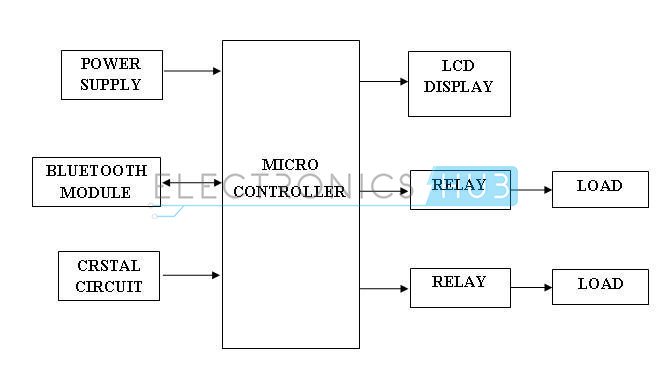
In this project Bluetooth module is interfaced to 8051 microcontroller. This Bluetooth receives the commands from the Android application device using wireless communication. The program which is written to the 8051 microcontroller communicates with Bluetooth module serially to receive the commands. Microcontroller switches the electrical loads automatically based on the commands received from the Bluetooth.Android Based Home Automation System Circuit Block Diagram:
Remote Password Operated Home Appliances Control – Block Diagram
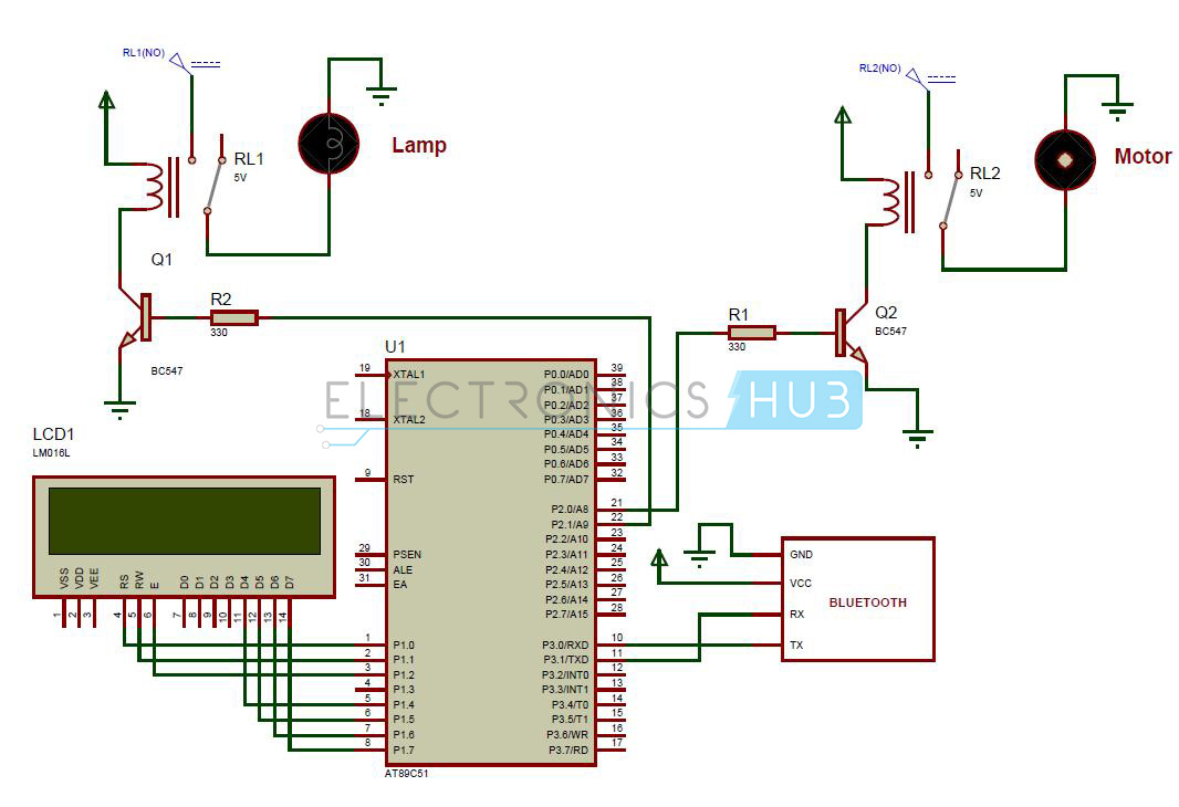
Bluetooth Controlled Electronic Home Appliances Circuit Diagram:
Bluetooth Controlled Electronic Home Appliances System – Circuit Diagram
- at89c51 controller
- 8051 programming board
- Programming cable
- DC battery or 12V,1A adaptor
- 16×2 LCD
- Bluetooth module
- 5V Relays – 2
- Lamp
- DC Motor
- BC 547 Transistors – 2
- 330 ohm resistors (1/4 watt) – 2
- Reset circuit
- Crystal circuit
- 5V DC power supply circuit
- Connecting wires
- Keil compiler
- Flash magic
- Proteus
- Android application file
Android Based Home Automation System Circuit Design:
This project consists of a microcontroller, 16 x 2 alphanumeric LCD, two 5V relays, a lamp, DC motor and Bluetooth module. Here at89c51 microcontroller is used. It is an 8 bit microcontroller and it requires supply voltage of 5V DC. Use 7805 power supply circuit to provide 5V DC to the microcontroller. We can use 9V DC battery or 12V, 1A adapter to provide the supply to the circuit. For the above circuit additionally you need to connect reset circuit and crystal circuit to the controller to work properly.In the above circuit LCD is used to indicate the status of electrical loads and also used to display received data from Bluetooth. Here LCD is interfaced to the PORT1 of the microcontroller in 4 bit mode.
Bluetooth module TX and RX pins are connected to the RXD and TXD pins of controller. Vcc pin is connected to the 5V and GND pin is connected to ground. Controller communicates with Bluetooth module using serial communication (UART protocol). Use a baud rate of 9600 to communicate with Bluetooth. If you want to change the Bluetooth name and password then you need to use Bluetooth AT commands.
Below are the few Bluetooth AT commands:
- AT — Responds OK. (Used to test the Bluetooth module)
- AT+RESET — Responds OK. (Used to reset the module)
- AT+NAME? — Responds with the module name.
- AT+NAME = <name> — Responds OK. Name should be less than or equal to 20 characters.
- AT+PSWD? — Responds with the existing password.
- AT+PSWD =<password> — Sets module pairing password.
Electrical loads (Lamp and DC motor) are connected to the P2.1 and P2.0 through the relays. Here relays are used to switch AC loads using small DC voltages. NPN transistors are used to drive the relays.
Remote Password Operated Home Appliances Control Project Algorithm:
- Initialize the LCD and UART protocol.
- Now read the data from Bluetooth module.
- Display the received data on LCD.
- Compare the received string with predefined strings and accordingly switch the electrical loads.
- Display the status of electrical loads on LCD.
Android based Home Automation System Circuit Simulation Video:
Watch the following output video of home automation system using android applications.How Bluetooth Controlled Electronic Home Appliances Circuit Works?
- Write the program to the projectin keil software and create .hex file.
- Burn program to the controller with help of flash magic.
- Now give the connections as per the circuit diagram.
- While making the connections, ensure that there is no any common connection between DC and AC supplies.
- Use 5V power supply circuit to provide regulated 5V DC to the microcontroller.
- Switch on the both AC and DC supplies.
- Now relay output pins gets 230v so do not touch the load connected pins.
- Install Bluetooth apk file in android device.
- Now pair android device with Bluetooth module.
- Send data to switch on the electrical loads.
Related Post: Also read the post – RF remote control for Home Appliances.
Bluetooth Controlled Home Automation System Project Output Video:
Bluetooth Controlled Electronic Home Appliances Project Applications:
- This project is used to control the various electrical appliances from the remote area.
- Using this project we can control all the loads using a single remote and a control unit.
Limitations of the Circuit:
- In this project the distance between control unit and android device is limited.
No comments:
Post a Comment